 I should have probably posted this back in September, but I have been too busy with work. My wife is the Box Tops for Education coordinator at our kids’ school, and in the summer she came up with the idea of building a “Robot Mascot” to motivate the children. Her vision of a Box Tops Robot was a combination of aluminum foil, lights, PVC pipe, and cardboard. Naturally, I envisioned something a little more technical and a lot more time consuming to build. Additionally, the recent trends in STEM at schools provided a great opportunity to inspire the students. We had a lot of concerns about the stability of the robot, as well as durability of the materials used. Anyone with kids can attest to their ability to destroy almost anything giving the right amount of time and tools.
Robot Requirements
- Programmatically controllable eyes
- Audio output from mouth cavity
- Informational Display Screen
- Remote access for updates
- Wifi / Cellular Connectivity
- Not easy to break or tip
- Smooth professional finish
I began to design the eye assembly since it was going to require a lot of testing and I didn’t own a 3D printer which would have made this a lot easier.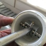 I decided to try using field hockey balls as the eyes, however; after boring a hole into the balls with a hole saw they lost rigidity. I tried to fix the rigidity issue by inserting a PVC sleeve into each eye ball. In order to give the eye a full range of movement, I constructed gimbal using an 1/2″ aluminum rod and 1″ square piping as shown in the image. Using 1/8″ brass rods and O-collars as the hinges to allow the eye to move freely in all directions. Although the eye was able to move in all directions it had serious flaws that weren’t discovered until trying to attach control rods for actuators.
 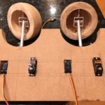 There simply wasn’t enough room for the ball joints to move freely and the control rods would strike the side of eye limiting it’s movement. Reducing the 1/2″ aluminum rod to a 1/4″ aluminum rod fixed the issue with the ball joints, however; it didn’t fix the issue with the outer control rods striking the inner housing of the eye. I decided to start over with hard wood balls which provided more rigidity and added free space for the control rods. Using a drill press, custom jig and a hole saw to hollow out the inside of the ball. We will get back to the eyes in a bit.
The Body and Head
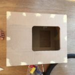
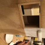
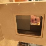
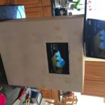
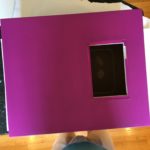
The body and the head were made from 3/4″ MDF I bought at Home Depot. Using a jigsaw, I cut out an access panel on the back of the robot and another for an LCD screen on the front of the robot. These cut outs were later routed to provide a recess to allow the LCD glass to inlay into the body and for the back access panel to lay flush. The images below show the progress from the rough cut to the routed edges and the head, eye and mouth holes. Inlayed magnets were used to attach the head and body access panels.
Testing, Fitting, and Painting
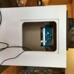
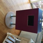
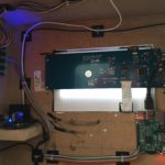
The images below show the process of testing and fitting various parts of the robot. There was a lot of honing and adjustment that occurred along the way and it’s not easily reflected in this post.
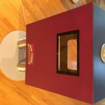
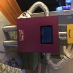
The following images show the added glass inlay, external USB ports, and LCD screen.
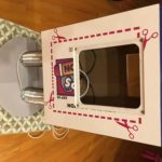
The back of the robot looks like a Box Tops coupon. I created an Adobe illustrator template and printed it to vinyl and attached it with 3M adhesive spray.
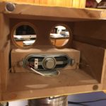
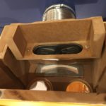
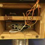
I created a speaker box with lock pins to prevent it from sliding back once all of the components are in place. The eyes slide in on an MDF rail so they can be easily removed for maintenance and the 1/4″ aluminum rods are glued into the MDF with epoxy.
The following video demonstrates the movement of the unpainted eyes.
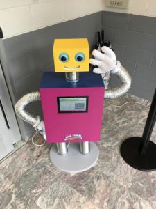
The final robot is shown below.

